
components mounted on a PCB prototype
Mounting components on a PCB prototype is a critical step in the PCB manufacturing process, as it directly affects the functionality and performance of the final product. A PCB prototype is a preliminary version of a printed circuit board created to test and validate the design before mass production. The process of mounting components on a PCB prototype involves placing and soldering various electronic components onto the board, ensuring that all connections are made correctly and securely. There are different methods for mounting components, and the choice of method depends on the type of components used, the complexity of the design, and the specific requirements of the prototype.
The first step in mounting components on a pcb prototype is to prepare the board and components. The PCB is usually manufactured with pre-drilled holes and pads for surface mount or through-hole components, depending on the design. These pads serve as the connection points where the components will be mounted and soldered. For surface mount components, the pads are usually flat and are designed to accommodate the leads of the component. For through-hole components, the pads have holes that allow the component leads to pass through and be soldered on the opposite side of the PCB. In both cases, it is essential to ensure that the PCB prototype is free from contaminants, dust, or moisture that could affect the soldering process.
Once the PCB is prepared, the next step is to apply solder paste to the pads where surface mount components will be placed. Solder paste is a mixture of solder and flux, and it is applied using a stencil or a dispensing machine. The solder paste is carefully applied in precise amounts to ensure that it adheres to the pads without spilling over onto adjacent areas. After the solder paste is applied, the surface mount components are placed onto the pads using automated pick-and-place machines or manually with tweezers. The placement machine picks up the components and places them accurately on the board, ensuring that each component is aligned with its respective pad.
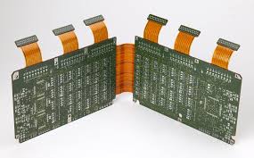
How are components mounted on a PCB prototype?
For through-hole components, the process is slightly different. These components have leads that pass through the PCB and are bent or trimmed on the other side of the board. The leads of the component are inserted into the pre-drilled holes, and the component is then positioned correctly on the board. Once the component is in place, it is secured by bending the leads on the opposite side of the board to hold it in position. This process is often done manually, but automated machines can also be used for high-volume production.
After the components are placed on the PCB prototype, the next step is to solder them in place. Soldering is the process of applying heat to the component leads and the solder paste, causing the paste to melt and form a solid electrical connection between the component and the PCB. For surface mount components, this process is typically done using a reflow soldering method, where the PCB is passed through a reflow oven. The oven gradually heats the board, melting the solder paste and forming the connections. For through-hole components, wave soldering or hand soldering is used. In wave soldering, the PCB is passed over a wave of molten solder, which flows into the holes and forms a strong bond. Hand soldering is often used for prototypes or small runs, where a soldering iron is used to melt the solder and create the connection manually.
Once the soldering process is complete, the PCB prototype is thoroughly inspected to ensure that all components are correctly mounted and soldered. Visual inspection is typically the first step, where an operator checks for any visible issues such as cold solder joints, solder bridges, or misplaced components. For more complex prototypes, automated optical inspection (AOI) machines can be used to check the quality of the solder joints and ensure that no defects are present. If any issues are identified, the components may need to be reflowed, re-soldered, or replaced.
Finally, after all the components have been successfully mounted and soldered, the PCB prototype undergoes functional testing. This testing ensures that the mounted components are working as intended and that the prototype functions correctly. If any issues are found during testing, adjustments may be made to the design, and a new PCB prototype may be created.